
 Share
Share
 Print
Print
|
|
|
|
|


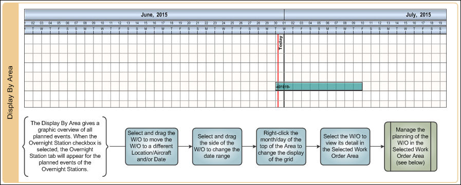
This Display By Area gives a graphic overview of all planned events, regardless of the tail number, sorted by location/site.
When the Overnight Station checkbox is selected from the Display Control Area, the Overnight Station tab will appear in the Display By Area. For additional information, refer to the Display Control Area, via A/C Planning Views which can be found in the Planning Training manual.

Please refer to the Interactive Planner View of this manual to see where the Display Controls Area is located on the Interactive Planner View.
The following information/options are available in this window:
_____________________________________________________________________________________
Red Vertical Line  indicator
Current date visual marker.
Different Location  icon
icon
The yellow icon at the beginning of a Work Order indicates that the work Order is in a different location than the scheduled flight. (i.e. The inbound flight is to MIA, but the Work Order is scheduled to take place in MCO).
Work Order Node 
The different colored Work Orders indicate the type of Work Order Category (i.e. Line, Heavy Maintenance, etc.) This can be set up via Settings/Explorer/System Transaction Code Explorer/Production/W/O Category. The color assigned to each Work Order category will be the color displayed in the Display By Area. The aircraft tail number appears prior to the description of the Work Order and Work Order number. The Work Order Node is represented by a six digit Work Order number and a Work Order description note that is defined in the Selected Work Order Area, Work Order tab. For more information refer to the Selected Work Order Area, Work Order tab section via the Planning Training Manual. To view additional W/O information e.g., A/C tail number, A/C S/N, start and completion dates, etc., select the Hypertext checkbox. For more information refer to the Display By Control Area, Hypertext checkbox via the Planning Training Manual.
Overdue E/C  icon
icon
The red arrow at the end of a Work Order indicates that an E/C within the Work Order is overdue.A Work Order containing an overdue E/C cannot be moved or changed. See below topic labeled 'Additional Functionality' for more information.
The Overdue E/C icon will disappear once the E/C has taken manual compliance and the Interactive Planner window has been refreshed. The user may refresh the window by exiting the window,and returning into it, or by selecting the Refresh Due At Info  Button, via the Engineering Control Tab, of the Selected Work Order Area section via the Planning Training Manual.
Next Lower Work Order  icon
icon
The black arrow linking two Work Orders displays the Next Lower Work Order.
_____________________________________________________________________________________
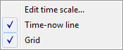
Right click in the blue/gray area as shown below:

The following options become available:
_____________________________________________________________________________________
Edit time scale...
Select the Edit time scale option. The Edit time scale pop-up appears. The user may use the below fields to change the time scale displayed in the Display By Area.
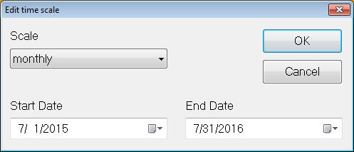
The user may also access the Edit time scale drop down by double clicking in the blue/gray area.
Scale - The user may select from one of the following time increments (monthly, weekly, daily) to change the display in the Display By Area:
Monthly - Select 'monthly' to view all planning jobs on a monthly calendar.
Weekly - Select 'weekly' to view all planning jobs on a weekly calendar.
Daily - Select 'daily' to view all planning jobs on a daily calendar.
Start Date - From the Start Date drop down, use the arrows to the left and right of the month to change the Start Date/month/year of the view in the Display By Area.
End Date - The End Date is used the same way as the Start Date.
Time-now line
Select the Time-now line to have the Today marker display as shown below:

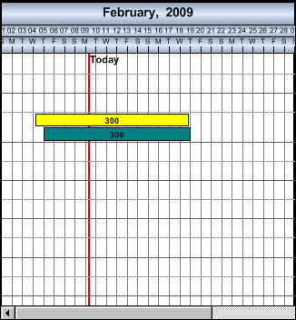
Grid
When the Grid option is selected, the display By Area is displayed with grid lines, as shown below:
_____________________________________________________________________________________
Additional Functionality:
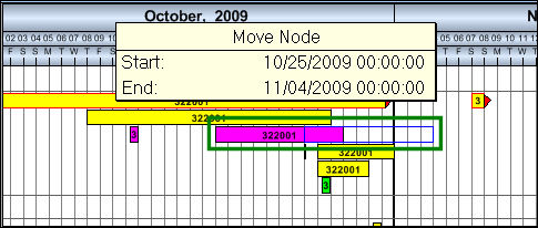
To move the Work Order from one Location or Aircraft to another, the Shift key must be held while the W/O is dragged.
 Display Man Hours Checkbox:
When selected, the average amount of required daily Man Hours for each Work Order in a Location/Site are listed under the Work Order. Man Hours for each W/O are determined by the amount of hours registered in the W/O Task Card Items.
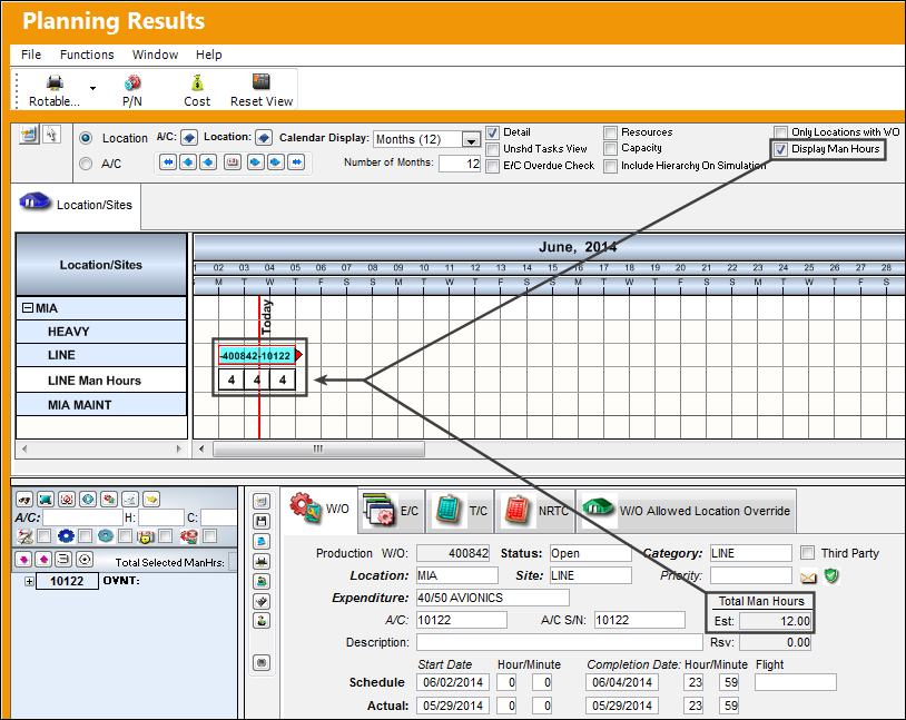
For this option to be available, Planning Switch  INTERACTPLANMANHOURS must be set to Yes. For detailed information refer to the Planning Switches Manual.
If the Exclude Man Hours from Interactive Planner checkbox is selected in the W/O, Optional tab, then that specific W/O's Man Hours will not be displayed in the Interactive Planner.
Share
Print
|
©1997-2026 Trax USA Corp. All rights reserved. This manual may not be copied, photocopied, reproduced, translated, or converted to any electronic or machine-readable form, in whole or in part, without prior written approval from Trax USA Corp. |
 |